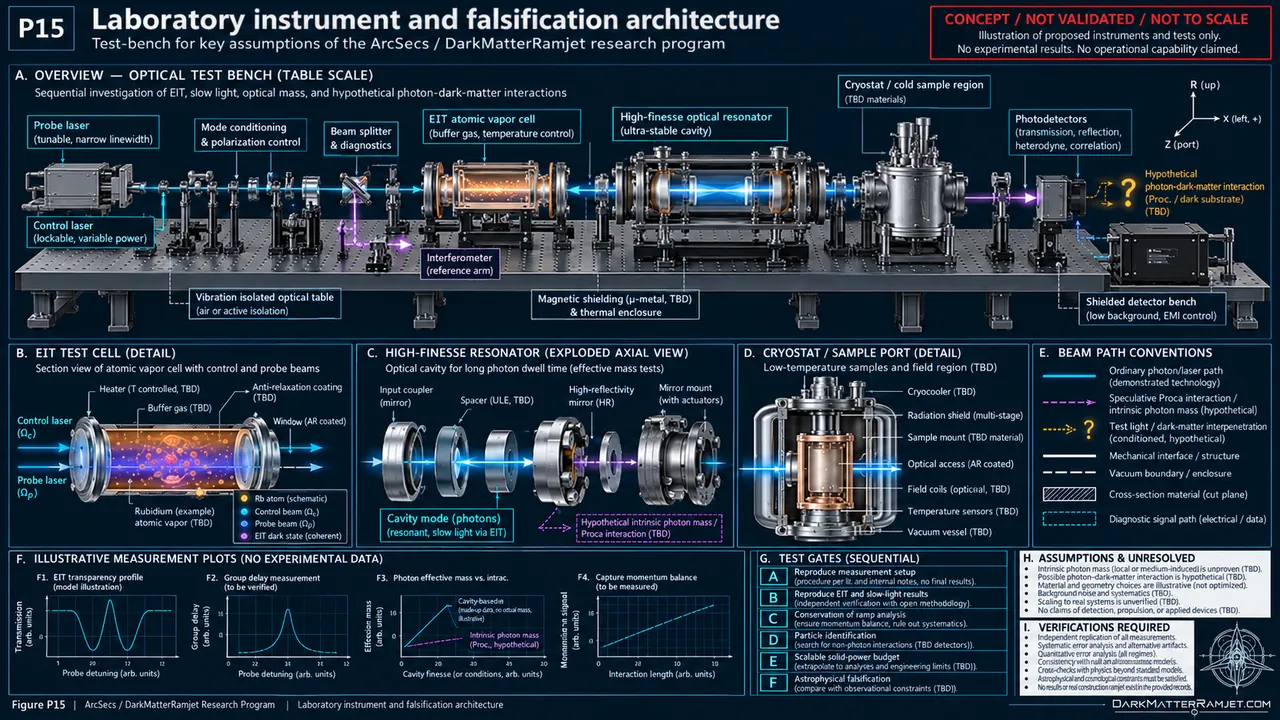
Projected intake field
A proposed wide capture field gathers ambient low-energy substrate into inward trajectories.
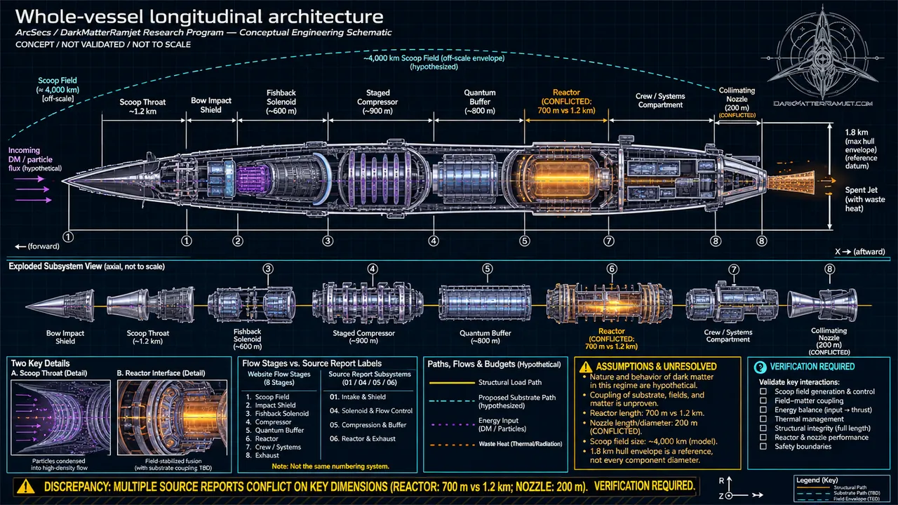
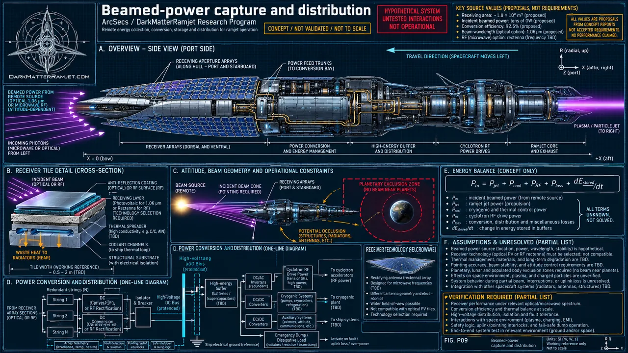
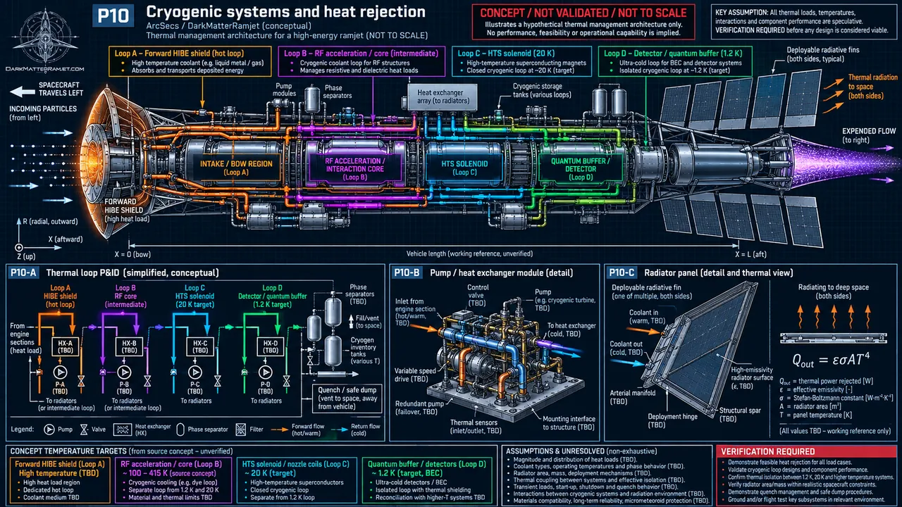
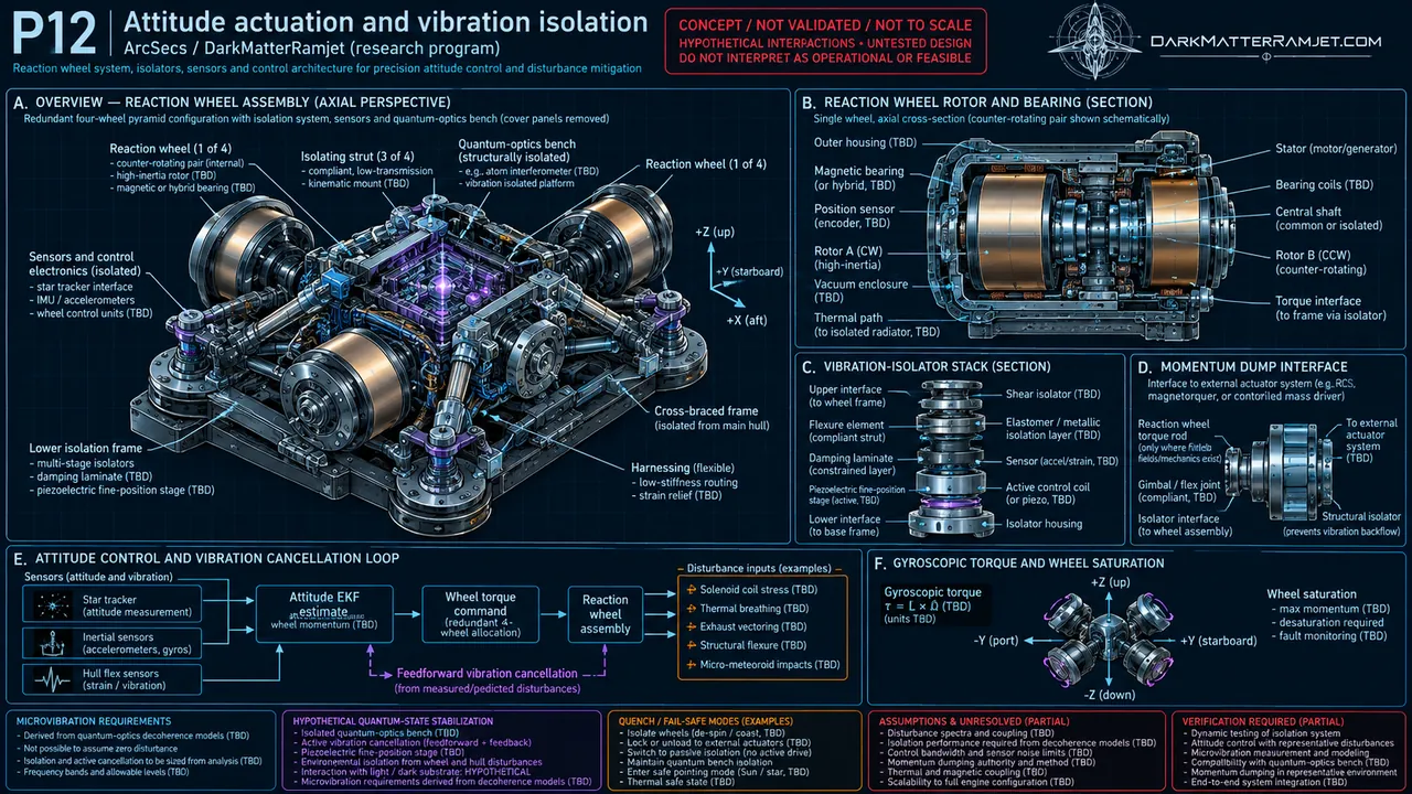
Research caveat: Hypothetical large-scale field coupling.READ SYSTEM GUIDE ↗ VIEW SCHEMATIC ↗The source notes describe a roughly 6.4 km ramjet with an extremely large projected collection field, layered protection, magnetic stages, storage, and a directed photon nozzle. These are design-study figures, not verified specifications.
Estimated full vehicle length in the project notes.
Inspect the geometry →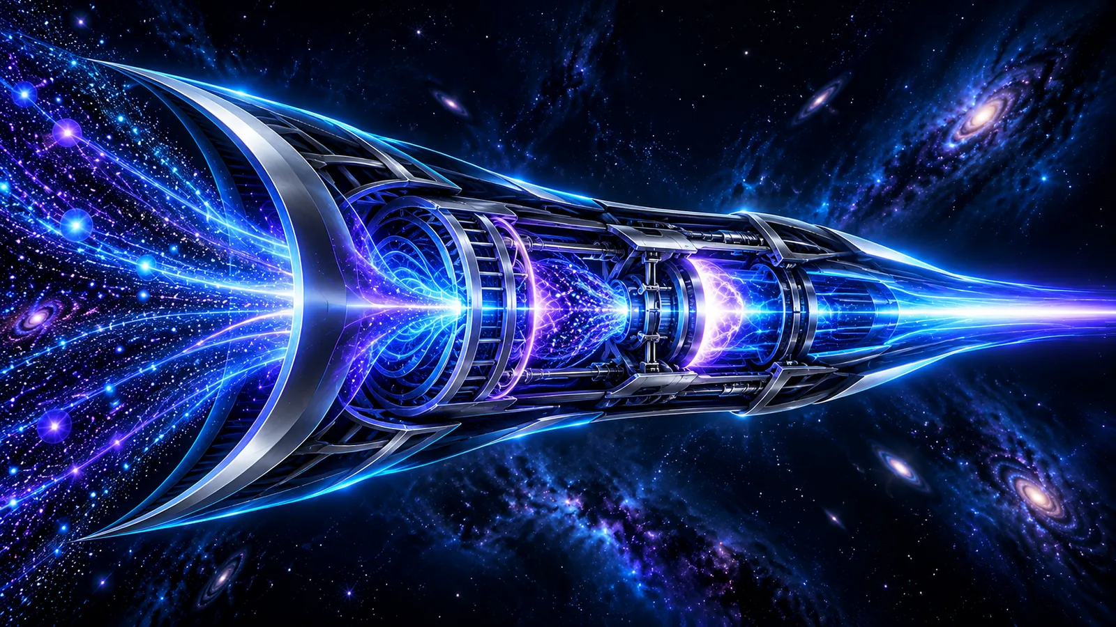
Values below are transcribed as proposals from the project architecture notes. Their feasibility has not been established.
| System | Proposed dimension | Role |
|---|---|---|
| Total length | ~6.4 km | Full vessel |
| Maximum hull diameter | ~1.8 km | Aft / housing cross-section |
| Projected scoop field | 4,000 km diameter | Hypothetical capture zone |
| Intake throat | ~1.2 km diameter | Substrate convergence |
| Solenoid section | ~600 m | Field shaping / proposed drag management |
| Compression | ~900 m | Multi-stage concentration |
| Stationary-light buffer | ~800 m | Proposed substrate storage |
| Reactor | ~700 m | Proposed re-energization |
| Exhaust collimator | ~200 m | Directed wake |
| Forward protective shield | ~120 m thick | Particle and thermal protection |
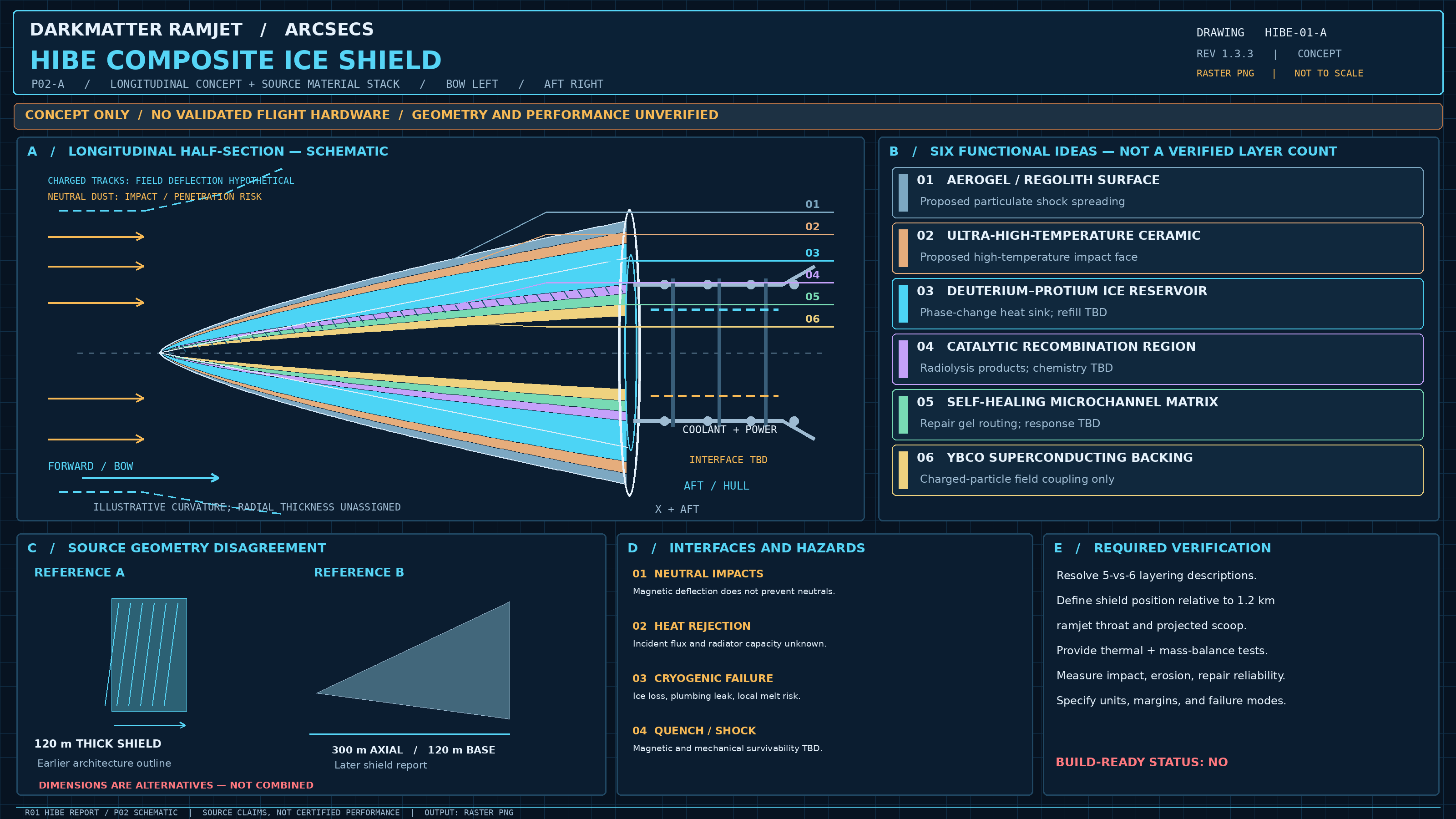
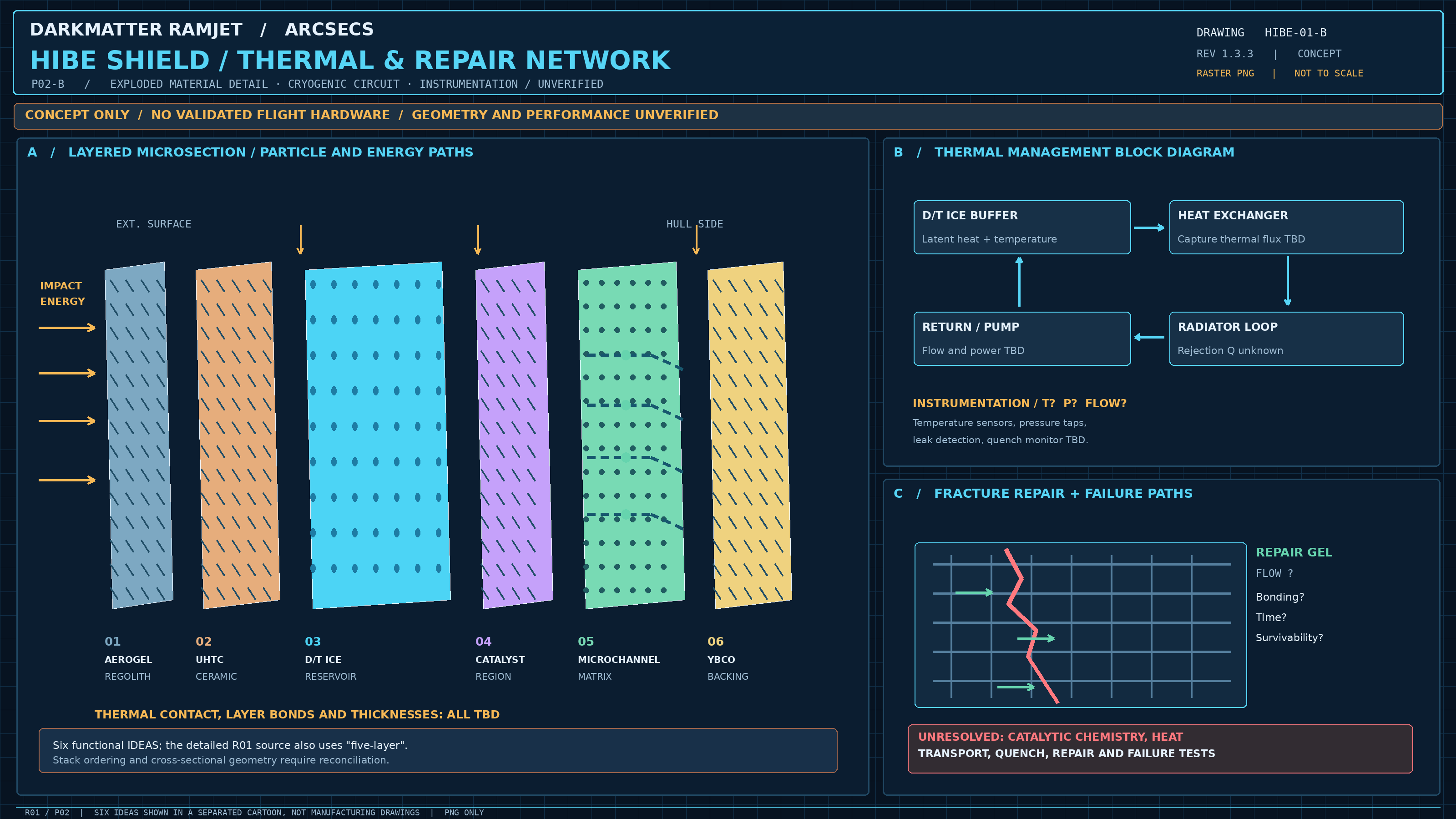
Two actual, raster-only subsystem drawings. The source reports disagree about shield size (120 m thickness versus 300 m axial / 120 m base) and about five versus six layers. These are unvalidated design-study diagrams, not build instructions.
Where each subsystem sits in the concept and what would have to be proved.
A proposed wide capture field gathers ambient low-energy substrate into inward trajectories.
Research caveat: Hypothetical large-scale field coupling.READ SYSTEM GUIDE ↗ VIEW SCHEMATIC ↗A layered bow shield protects the vessel from ordinary gas, dust and energetic impacts.
Research caveat: Material architecture is conceptual.READ SYSTEM GUIDE ↗ VIEW SCHEMATIC ↗The flow narrows into a controlled passage that conditions the incoming substrate.
Research caveat: Substrate interaction is not established.READ SYSTEM GUIDE ↗ VIEW SCHEMATIC ↗Superconducting structures are proposed to shape incoming trajectories and reduce drag.
Research caveat: No validated drag-decoupling mechanism.READ SYSTEM GUIDE ↗ VIEW SCHEMATIC ↗A sequence of field gradients is imagined to concentrate the incoming mass flow.
Research caveat: Energy costs and stability unquantified.READ SYSTEM GUIDE ↗ VIEW SCHEMATIC ↗A storage stage is inspired by dark-state polariton techniques in laboratory optical media.
Research caveat: Bulk space application is speculative.READ SYSTEM GUIDE ↗ VIEW SCHEMATIC ↗The conceptual reactor converts captured low-energy material into high-energy output.
Research caveat: No demonstrated conversion reaction.READ SYSTEM GUIDE ↗ VIEW SCHEMATIC ↗An aft collimator directs energy and momentum into a narrow thrust-producing wake.
Research caveat: Net thrust depends on a real energy budget.READ SYSTEM GUIDE ↗ VIEW SCHEMATIC ↗A realistic design would need field generation, heat rejection, material stress, interactions with ordinary matter, storage feasibility, conversion efficiency and rigorous momentum accounting. These are open challenges—not solved by the model or the source drawings.
See the validation roadmap →Enter the interactive lab and explore the eight proposed stages.
Rule-based guide. No experimental claims or AI model calls.