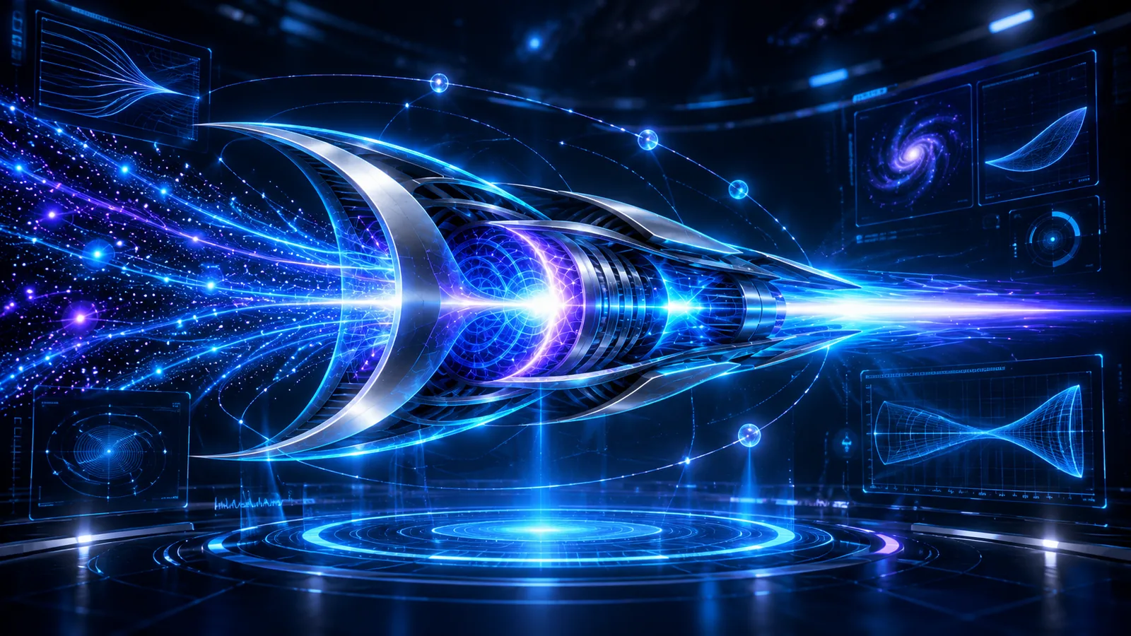
See the proposed flow from collection field to photon exhaust. Rotate the model, focus individual systems and tune conceptual operating parameters.
WEBGL · INTERACTIVE VISUAL MODEL Not a validated physical simulation
DMR / SYSTEM VISUALIZATIONLIVE RENDER
3D rendering is unavailable on this device.
Try a current browser with WebGL2 enabled. The stage descriptions and controls remain accessible.
FOCUS / FULL SYSTEM
All stages visible: collection, compression and exhaust.
DRAG TO ORBIT · SCROLL TO ZOOM
SYSTEM INSPECTION
Trace the eight-stage architecture
Choose a stage to highlight its approximate position within the vessel.
00 / OVERVIEWFull propulsion chain
Follow the illustrated dark substrate into the intake and the energized beam out of the aft nozzle.
SIMULATION VISUAL LANGUAGEIllustrative visualization of the simulation interface. Live WebGL controls are separate from this artwork.
WHAT THE NUMBERS MEAN
A model of a proposal. Not a prediction.
Captured flow index = normalized density × normalized capture efficiency. Output index = captured flow × normalized conversion intensity. Collection loss = 100% − capture efficiency. These are dimensionless teaching controls and do not model thrust, energy conservation, or relativity.